


UV-Vis Spectroscopy: How It Works, What Its Pros and Cons Are, and How It Can Be Used
UV-Vis spectroscopy is used in many scientific fields for everything from measuring and assessing the amount and purity of nucleic acids to drug discovery. It finds use as well in quality control for the beverage sector and chemical research. This work discusses the examination of the UV-Vis spectroscopy data.Furthermore covered are the advantages and disadvantages of the method coupled with instances of its application.
Why may UV-Vis spectroscopy be useful?
The UV-Vis spectroscopy analytical method compares a sample to a reference or blank sample by measuring the amount of different UV or visible light bands absorbed by or transmitted through a substance. This trait is affected by the make-up of the sample, which could tell you what is in the sample and how concentrated it is. Light is needed for this spectroscopy method, so let’s start by looking at what light is made of.
Light has a certain amount of energy that is opposite to how long its wavelength is. In this way, light with shorter wavelengths has more energy than light with longer wavelengths. Absorption occurs when electrons in a substance are moved to a higher energy state. Getting electrons to a higher energy state in different bonding conditions in a material requires varying amounts of energy. This is the reason why different things absorb light at different wavelengths.Visible light that our eyes can see ranges from around 380 nm, or violet, to 780 nm, or red.Up to roughly 100 nm, UV radiation is shorter than visible light.Thus, the length of a wave can characterize light.This could be helpful in UV-Vis spectroscopy to identify or assess various substances and determine the wavelengths that absorb light the most (more details are available in the UV-Vis spectroscopy Applications section).
In a specific sense, the UV-Vis spectrophotometer works.
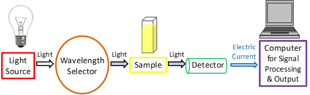
Even though there are numerous types of UV-Vis spectrophotometers, let’s take a look at the key components, as illustrated in Figure 1, to obtain a better understanding of how they operate.
A simplified schematic depicting the key components of a UV-Vis spectrophotometer. This picture shows the path of light from the light source to the wavelength selection, sample, and detector before it is processed as a signal.
A simplified diagram of the main parts of a UV-Vis spectrophotometer is shown in Figure 1.
Source of light
For a light-based method to work, it needs a steady source of light that can send out light at many different colours. Light sources that are very bright, both in the UV and visible bands, often use a single xenon lamp. To the other hand, xenon lights are more expensive and don’t last as long as tungsten and halogen lamps.
Visible light is usually provided by a tungsten or halogen lamp in instruments with two lamps, while UV light is usually provided by a deuterium lamp. The light source in the instrument has to change during measurement because it needs two different light sources to scan both wavelengths. In real life, this changeover usually takes place during the scan between 300 and 350 nm, when both light sources give off similar amounts of light and the change can go more smoothly.
Choosing a wavelength
Next, from the wide range of wavelengths that the light source gives off, certain wavelengths must be chosen that are right for the type of sample and the analyte that needs to be detected. Some ways to do this are listed below:
- Monochromators: A monochromator only lets a small range of colours pass through it. There are a lot of different types of diffraction gratings that can be used to choose the range of light that is needed. The groove frequency of a diffraction grating is usually measured by the number of grooves per millimetre. A higher groove frequency gives you better optical clarity, but it also limits the range of wavelengths that you can use. A lower groove frequency gives you a wider range of wavelengths that you can use, but it also makes the optical sharpness worse. For UV-Vis spectroscopy, grooves with 300 to 2000 per mm are fine, but grooves with at least 1200 per mm are more common. There are small flaws in the diffraction grating and the optical setup that can affect the accuracy of the spectroscopic readings. Because of this, ruled diffraction gratings usually have more flaws than blazed holographic diffraction gratings.3 Blazed holographic diffraction gratings usually give much better results.3
- Absorption filters: These are usually made of coloured glass or plastic that are meant to soak up certain wavelengths of light.2
- People often use interference filters, which are also known as dichroic filters. They are made of many thin layers of insulating material that interact with each other. As a wavelength selector, these filters can be used to get rid of wavelengths that aren’t wanted by harmful interference.1,2
- Cutoff filters: These filters let light pass through or not pass through at all, depending on the wavelength. Interference filters are often used to make these work.
Bandpass filters: These filters let a range of colours pass through. They can be made by putting shortpass and longpass filters together.
Because they can do so many things, monochromators are most often used for this process. However, filters are often used with monochromators to further narrow the wavelengths of light that are chosen. This makes readings more accurate and boosts the signal-to-noise ratio.
Analysis of samples
The light then goes through a sample, no matter what colour selector is used in the spectrophotometer. The “blank sample” or reference sample must always be measured. This can be a cuvette filled with the same liquid that was used to prepare the sample. Any measures are done with an aqueous buffered solution that has the sample in it. The reference is an aqueous buffered solution that doesn’t have the substance of interest in it. The clean culture media would be used as a guide when looking at bacterial cultures. Following that, the instrument will immediately use the reference sample signal to help get the real absorbance values of the analytes.
When you do UV–Vis spectroscopy studies, you need to know about the things you use and the conditions they are in. For instance, most plastic cuvettes shouldn’t be used for UV absorption tests since plastic absorbs UV light in general. Glass can be used as a screen, blocking most UVC (100–280 nm)2 and UVB (280–315 nm)2 but letting some UVA (315–400 nm)2 pass through. Because most UV light can’t pass through quartz, sample holders made of quartz are needed for UV testing. Light waves shorter than about 200 nm are absorbed by molecular oxygen in the air, so you can also think of it as a screen. For readings with wavelengths smaller than 200 nm, you need a special, more expensive setup. Usually, this includes an optical system filled with pure argon gas. You can also get tools that don’t need cuvettes and can analyse very small amounts of sample, like DNA or RNA.
Find Out
A detector turns the light into an electric signal that can be read after it has gone through the sample. Photoelectric films or semiconductors are often used to make detectors.
When light hits a photoelectric layer, it sends out negatively charged electrons. When electrons are thrown out, an electric current is made that is related to the brightness of the light. One of the most common detectors used in UV-Vis spectroscopy is the photomultiplier tube (PMT).2,5 A PMT works by ejecting electrons when it comes into contact with light, and then sequentially multiplying those electrons to make a larger electric current.4 PMT detectors are especially good at picking up very low levels of light.
Semiconductors may conduct electric currents proportionate to the brightness of the light that strike them. Charge-coupled devices (CCDs) are among the most often used semiconductor-based detectors.Two such examples are photodiodes 2 and 6.
The monitor sends an electric current, which is then picked up by a signal processor and sent to a computer or screen. Figures 2 and 3 are simpler schematic diagrams of how UV-Vis spectrophotometers can be set up.
A UV-Vis spectroscopy device based on a cuvette is shown in this diagram.
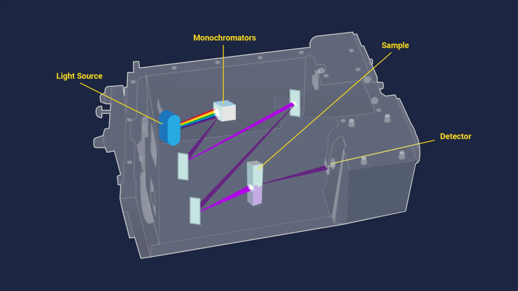
Figure 2 shows a schematic of a UV-Vis spectroscopy system built on a cuvette. Thanks to Technology Networks
A UV-Vis spectroscopy device without a cuvette is shown in this diagram.
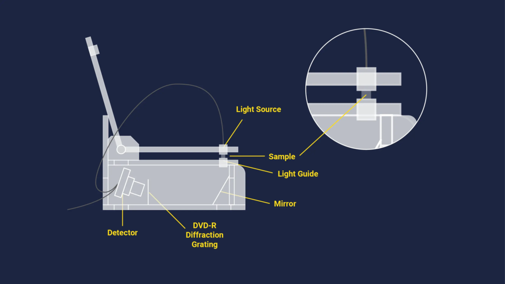
Figure 3: A schematic drawing of a UV-Vis spectroscopy setup that doesn’t use cuvettes.With thanks to Technology Networks.Ten
Examining absorbance units, UV-Vis spectra, and other data
UV-Vis spectroscopy data may be displayed as a graph of absorbance, optical density, or transparency as a function of wavelength.On a graph showing the data, wavelength is typically on the x-axis and absorption on the y-axis.Most of the time we refer to this curve as a “absorption spectrum”; Figure 4 illustrates one.
This sample of an absorption spectrum was made with a UV-Vis spectrophotometer. The broken down haemoglobin was dissolved in neutral pH phosphate buffer.

An absorption curve produced with a UV-Vis spectrophotometer is shown in Figure 4. Haemoglobin that had gone bad was dissolved in neutral pH phosphate buffer. Thanks to Dr. Justin Tom.
Based on the UV-Vis spectrophotometer equipment we looked at earlier in this piece, it seems likely that the amount of light that hits the sample will be directly related to how bright the light is.
To find the absorbance (A), divide the intensity of the light before it passes through the sample (Io) by the intensity of the light after it passes through the sample (I). Transmittance (T) is another name for the fraction I split by Io.It indicates how much light has travelled through a sample. Beer-Lambert’s rule can be used to determine the concentration of the sample (c) following measurement of the absorbance (A) if you know the molar absorptivity (ε) and the route length (L). If you want to talk about ε, you use the units L mol‑1 cm‑1, L has units of cm, and c has units of mol L‑1. Because of this, A doesn’t have any units.
AU is sometimes used to stand for random units or absorbance units, but this is not recommended.
If there is a linear relationship between a measured set of standard solutions having the same substance and the concentration of the substance, Beer–Lambert’s law can be used to find the concentration.Equation 1.5.9 connects mathematically Beer-Lambert’s rule, transmittance, and the amount of light detected by the device.

This formula relates mathematically transmittance, light intensities measured by the device, and Beer-Lambert’s law.
Equations 1 provides a set of formulas that show how transmittance, measured light intensities, Beer-Lambert’s law, and absorbance A are related.
Absorbance and optical density (OD) are sometimes used interchangeably to mean the same thing. One can quantify the amount of light energy lost in an optical component using either absorbance or OD. However, OD takes into account light scattering loss while absorbance does not. It is possible to get a good idea of OD straight from absorbance and Beer–Lambert’s law if there isn’t much light scattering in the measurement.
It is important to know the experimental settings when taking measurements. Most of the time, cuvettes that are made for a 1 cm path length are used. There are times when there isn’t much sample to look at, so path lengths as short as 1 mm are needed.Stay within the dynamic range of the instrument and below 1 if you must measure anything. This is so because an absorption of 1 indicates that 10% of the light entering the sample was passed through and 90% was absorbed by it. Some UV-Vis spectrophotometers enable too little light to reach the receiver, making it impossible to measure tiny amounts of light with reliability.Two easy fixes for this problem are to shorten the travel or dilute the sample.
As was already said, a baseline spectrum taken with a “blank” reference solution is essential. If there was no equipment problem at all, the baseline should display 0% absorbance at any wavelength inspected. Conversely, in real life the baseline spectrum will typically have some extremely tiny positive and negative absorbance values. The best way to get the real absorbance values is for the software to immediately take these small absorbance values away from the sample absorbance values for each wavelength of light.1
Depending on the reason for the study, it might be helpful to make a calibration curve. It takes some extra work and data analysis to make a calibration curve, but it is very helpful to correctly figure out how much of a certain substance is in a sample by measuring its absorbance. There are, however, many times when you don’t need a calibration curve. For example, you don’t need one to take OD readings for growing bacteria or absorbance ratios at certain wavelengths to check the purity of nucleic acids or identify certain drugs.
In UV-Vis spectroscopy, the wavelength that the substance of interest absorbs the most light at is picked for study. This choice gives the best sensitivity because it gets the biggest reaction for a certain amount of analyte.1 Figure 5 shows an example of Food Green 3’s UV-Vis absorption spectrum and a calibration curve made with standard solutions that goes with it. It is important to note that the Food Green 3 dye has two strongest absorption peaks. The weaker peak is at 435 nm, and the stronger peak is at 619 nm. For study, the absorbance peak at 619 nm was chosen because it gave the best sensitivity when trying to figure out an unknown concentration of Food Green 3. We made standard solutions with a range of known concentrations by diluting a stock solution. We then measured the absorbance of these solutions and plotted them on a graph of absorbance versus concentration to find a number that connects concentration and absorbance. A least squares linear regression equation was used to make a calibration graph. It fits better when the data points are close to a straight line. In order to show that there was no absorbance when there was no dye, the y intercept in the straight line solution was set to zero. Based on the observed absorbance (variable y), the equation in Figure 5 is used to figure out how much Food Green 3 is in a sample that is unknown.
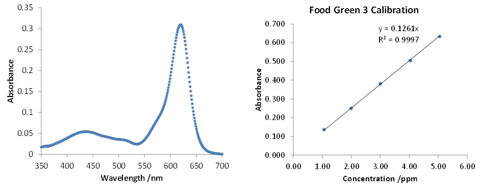
The graph on the left shows a UV-Vis spectrum of Food Green 3 that was taken from a sample. A least squares linear regression equation was used to make the calibration curve on the right graph from standard diluted solutions of Food Green 3.
There is a UV-Vis spectrum of Food Green 3 taken from a sample in Figure 5. It can be seen on the left line. A least squares linear regression equation was used to make the calibration curve on the right graph from standard diluted solutions of Food Green 3. Thanks to Dr. Justin Tom.
To figure out how sensitive the system is when making a calibration curve for data analysis, the graph of absorption versus concentration can be used. The slope from the line of best fit shows how sensitive something is when a linear least squares regression equation is used. The sensitivity goes up as the slope goes up. Sensitivity is the skill to tell the difference between small changes in the concentration of the sample. Beer–Lambert’s Law says that the molar absorptivity ε can give you some information about the sensitivity. If you know the ε values ahead of time, it can help you figure out how much of a sample you need, especially if samples are scarce or expensive.
For accuracy and to follow best practices, UV–Vis spectroscopy tests and results should be done more than once. It is normal to do at least three replicate trials when looking at the same sample more than once. In some fields of work, many more replicate trials are needed. A calculated number, like the concentration of a sample whose value is unknown, is typically given as an average with a standard deviation. To make sure that measurements are accurate and of good quality, they must be able to be repeated. How accurate the method and measurements are can be judged by the standard deviation, the relative standard deviation, or the coefficient of variation. A low deviation or variation means that the accuracy and dependability are better.
What UV-Vis spectroscopy can and can’t do
There is no such thing as a perfect method, and UV–Vis spectroscopy is no different. The method is popular because of the following main benefits.
- The method doesn’t damage the sample, so it can be used again or sent for more processing or analysis.
- It is easy to add measurements to experimental methods because they can be made quickly.
- Instruments are simple to use and don’t need much training before they can be used.
- Data analysis usually doesn’t need a lot of processing power, which means that users don’t need much training.
- The device is usually not expensive to buy and run, which means that many labs can use it.
There are a lot of good things about this method, but there are also some bad things:
- Stray light—In a real instrument, the wavelength selectors aren’t perfect, so a small amount of light from a wide range of wavelengths may still be transmitted from the light source,1 which could lead to serious measurement errors.9 Stray light can also come from the environment or a part of the instrument that isn’t tight enough.1
- Light scattering—Solids that are held in liquid samples often cause light scattering, which can lead to big mistakes in measurements. If there are bubbles in the cuvette or sample, they will scatter the light, making the data impossible to repeat.
- Multiple absorbed species can cause interference— For example, a sample might have more than one type of chlorophyll, which is a green pigment. When looked at together in the same sample, the spectra of the different chlorophylls will overlap. For a correct quantitative study, each type of chemical should be taken out of the sample and looked at on its own.
- Geometrical considerations—If any of the instrument’s parts are misaligned, especially the cuvette that holds the sample, the results may not be repeatable and will be wrong. Because of this, it is important that for each measurement, every part of the device is lined up in the same direction and put in the same place. To avoid misuse, it is usually suggested that users get some basic training.
UV-Vis spectroscopy has many uses.
UV-Vis has been used for many things and conditions, such as, but not limited to:
Look at DNA and RNA
For example, one very common use is quickly checking the purity and quantity of RNA and DNA. Within Table 1, you can see a list of the bands they used and what they meant. When getting DNA or RNA ready for sequencing or other steps further down the line, it is important to make sure that the samples are not contaminated with each other or with protein or chemicals that got into the samples during the isolation process.
In Table 2, you can see how the 260/280 absorbance ratio can help you find possible contamination in nucleic acid data. In general, the 260/280 ratio for pure DNA is 1.8, while the ratio for pure RNA is 2.0. RNA replaces thymine with uracil, which has a lower 260/280 ratio than uracil. This means that pure DNA has a lower 260/280 ratio than RNA. Samples with proteins will have a smaller 260/280 ratio because they absorb more light at 280 nm.
Wavelength used in absorbance analysisin nanometers | What does UV absorbance at this wavelength indicate the presence of? | What causes UV absorbance at this wavelength? |
| 230 | Protein | Protein shape10 |
| 260 | DNA and RNA | Adenine, guanine, cytosine, thymine, uracil |
| 280 | Protein | Mostly tryptophan and tyrosine |
In Table 1, you can see a summary of the useful UV absorbance for figuring out the 260/280 and 260/230 absorbance ratios.
| Absorbance ratio | Typical values |
| 260/280 | 1.8 absorbance ratio typical for pure DNA2.0 absorbance ratio typical for pure RNA |
| 260/230 | Absorbance ratio varies; 2.15 to 2.50 typical for RNA and DNA11 |
This is a list of the predicted UV absorbance ratios for DNA and RNA analysis (Table 2).
The 260/230 absorbance ratio can also be used to check the quality of DNA and RNA samples. It may show if the samples are contaminated with chemicals or proteins. Proteins can absorb light at 230 nm, which lowers the 260/230 ratio and shows that DNA and RNA samples contain proteins.10 Guanidinium thiocyanate and guanidinium isothiocyanate are two common compounds used to clean nucleic acids, and they also strongly absorb at 230 nm, which lowers the 260/230 absorbance ratio.
Analysis of pharmaceuticals
One big area where UV-Vis spectroscopy is used a lot is in the pharmaceutical industry12,13,14,15,16,17. Specifically, using mathematical derivatives to process UV-Vis spectra lets you separate overlapping absorbance peaks in the original spectra to find specific pharmaceutical compounds.12,17 For instance, benzocaine, an anaesthetic, and chlortetracycline, an antibiotic, can be found together in commercial veterinary powder formulations by applying
Culture of bacteria
UV-Vis spectroscopy is often used to grow germs in a lab. Scientists often use a wavelength of 600 nm to quickly and accurately measure OD to figure out the number of cells present and to keep track of their growth.18 This wavelength is commonly used and preferred because it doesn’t damage the cells when they need to be used for more experiments.
Drinks analysis
An other common application of UV-Vis spectroscopy is the identification of certain compounds in beverages. Caffeine levels are regulated by law, and UV light can assist determine those limits. Finding some colored compounds, such as anthocyanin, which is present in blueberries, strawberries, blackberries, and cherries, for quality control using UV-Vis absorbance is simple when matching known peak absorption wavelengths in wine.$20
There are further applications.
Numerous other disciplines could also benefit from this approach. For instance, measuring a colour index can be used to keep an eye on transformer oil as a safety measure.21 Measuring the absorbance of haemoglobin to find out how much haemoglobin is present could be used in cancer research.22 In wastewater treatment, UV-Vis spectroscopy can be used in kinetic and monitoring studies to check that certain dyes or dye by-products have been removed properly by comparing their spectra over time.23 It is a
UV–Vis spectroscopy is also very useful for some more specialised studies. Following changes in the wavelength that corresponds to the peak absorbance can help with looking at specific changes in structural proteins24,25,26 and figuring out what’s in a battery27. Changes in peak absorbance wavelengths can also help with more modern tasks like characterising very small nanoparticles28,29. This method has a huge number of uses that don’t seem to end.